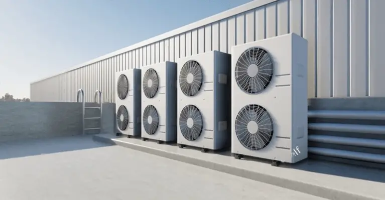
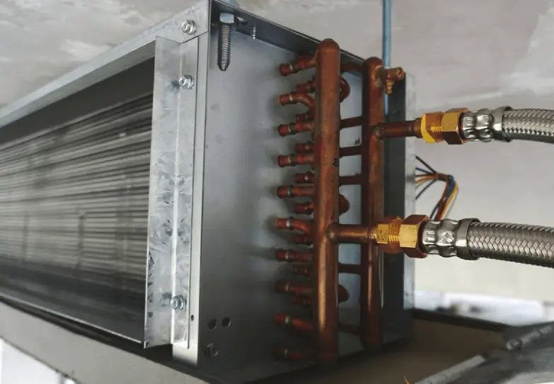
This method statement outlines the systematic procedure for the proper installation of Fan Coil Units (FCUs) and Packaged Air Conditioning Units, including associated refrigerant pipework. The purpose of this method statement is to ensure that the installation is in compliance with relevant requirements, adheres to manufacturer instructions, and aligns with the contract documents and technical specifications.
Table of Contents
- Scope of Work
- Personnel Responsibility
- Pre-Installation Requirements
- Method of FCU Installation
- Method Statement for Condensing Unit Installation
- Flaring Technique for Connections to FCU
- Method Statement for Compression Coupling Joint
- Installation of Aeroquip Valve to Condensing Unit
- Installation of Condensate Drain Pipes
- Refrigerant Pipework Pressure Test & Criteria
- Insulation of Condensate Drain Pipe
- Reference Documents
Scope of Work
The HVAC method statement covers the following:
- Fan Coil Units (FCUs) of all types.
- Split floor Package Air Conditioner.
- Split ceiling Package Air Conditioner.
- Refrigerant Pipework.
- U-PVC Pipework.
Personnel Responsibility
The responsibility for the successful implementation of this method statement lies with the Construction Manager, Mechanical Engineer, and Site Supervisor.
Pre-Installation Requirements
All materials and documentation specific to each section of work will be thoroughly checked by the construction department before commencing the installation. This ensures the materials comply with client approval and applicable specifications.
Pre-inspections will be carried out on all materials before they leave the storage area.
The areas and access points for construction activities will be inspected to confirm their suitability.

Method of FCU Installation
All lifting, handling, and installation procedures will strictly adhere to the manufacturer’s instructions, ensuring the units are not subjected to undue stress.
Ensure that the correct model and type of FCU are being installed.
Floor-mounted units will be securely bolted to the “Housekeeping Pad” using anchor bolts, with rubber-in-shear isolators providing a minimum deflection of 5mm.
Suspended units with fan motors up to 7.5 kW will be isolated using spring isolators with a minimum static deflection of 20mm. For higher-rated fan motors, the minimum static deflection will be 40mm.
Vibration isolators will be installed internally on all reciprocating equipment in packaged units.
The unit will be positioned according to the approved shop drawing, and support structures will be of adequate strength and in line with the drawings.
Lift and position the unit safely using appropriate lifting gear.
Firmly secure the unit to the supports and ensure it is level horizontally for proper operation and maintenance.
Method Statement for Condensing Unit Installation
Check and ensure that the housekeeping pads are level and in the correct location as per the approved layout drawing.
Securely place and bolt the condensing unit to the housekeeping pads, ensuring proper leveling in all directions and installing anti-vibration pads as per approved construction drawings.
Ensure adequate ventilation around the unit to facilitate airflow.
Follow approved design details for the installation of liquid loops or oil traps in the refrigerant pipework based on the positions and dimensions of the outdoor and indoor units.
Flaring Technique for Connections to FCU
Cut the copper refrigerant pipework carefully using a pipe cutter, avoiding excessive force to prevent pipe distortion.
Remove burrs from the flaring end to ensure a smooth surface that prevents refrigerant leaks.
Fix the pipe firmly on the flare die and match the centers of the flare die and flaring punch before tightening the flaring punch fully.
Method Statement for Compression Coupling Joint
Place the compression joint nut over the copper tube before or after the flaring operation.
When making the final connection, tighten the nut by hand and use the correct size spanner to secure it firmly to the tube without causing pipe distortion.
Installation of Aeroquip Valve to Condensing Unit
Lubricate the male half of the diaphragm and synthetic rubber seal with refrigerant oil.
Thread coupling halves together by hand to ensure proper mating of threads.
Tighten coupling bodies until a definite resistance is felt and then mark the coupling union nut to the bulkhead for additional 1/4 turn to form a leak-proof joint.

Installation of Condensate Drain Pipes
Factory-standard insulated drain pans will be provided with each fan coil unit.
Connect the piped drain to the bottom of the pan via an approved union and a sealed trap to the exterior of the unit housing.
Ensure that the trap is configured and sized appropriately to maintain a seal under various operating conditions.
The condensate discharge will be directed to the nearest drain point, visible for inspection and maintenance.
Refrigerant Pipework Pressure Test & Criteria
Conduct a pressure test on the flare connections at both the Fan Coil Unit and Condensing Unit.
Isolate valves at the Condensing Unit before connecting the line to nitrogen, setting the system pressure to approximately 0.2 KPa.
Purge air from the system using nitrogen.
Check for leaks using a foaming liquid leak detector agent.
Record and compare the system pressure results at different stages of the pressure test.
Insulation of Condensate Drain Pipe
Insulate condensate drain pipework with Nitrile Rubber insulation, 19mm thick with a dull matt finish.
Cut the insulation appropriately for fitting traps and end of runs, ensuring neat and sealed butt joints.
Reference Documents
- FCU Installation Tracking Check List.
- Approved Shop Drawing.
- Inspection and Testing & Commissioning Plan.
- Manufacturer’s Instructions for the Packaged Air Conditioning Unit / Fan Coil Units.
tag: # FCU, fan coil units, method statement for fan coil units
